Home
/ Mini Xlr Wiring Diagram : How To Wire An Xlr To A 1 4 Trs Stereo Jack Plug : Xlr pin 1 = shield, amphenol pin 1.
Mini Xlr Wiring Diagram : How To Wire An Xlr To A 1 4 Trs Stereo Jack Plug : Xlr pin 1 = shield, amphenol pin 1.
Mini Xlr Wiring Diagram : How To Wire An Xlr To A 1 4 Trs Stereo Jack Plug : Xlr pin 1 = shield, amphenol pin 1.. (the rear view is the end you solder from) here are the connections on each pin: Probably the most common wiring fault is a whisker from one wire touching the adjacent terminal. The mini xlr has become quite popular in the headphone market as it is relatively small, it locks in place, and the connections are more reliable than your average trs. #standard xlr wiring diagram yamaha. Xlr to 1/4 inch mono wiring diagram.
Choose hardwired option for p48. Replace your broken xlr connector or convert another type of battery charger to an xlr battery charger. Mx xlr adapters do not suffer from inse. Mx 3 pin 4 pin 5 pin mini xlr type connector is a type of connector used for many professional audio applications. The adapter cable on top is for connecting to an amplifier's speaker out terminals.
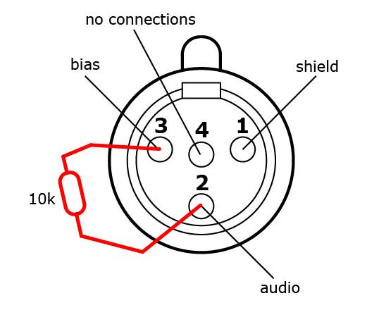
Cxj05 Classic Balanced Mic Cable For Mini Jack Propaudio from propaudio.com 10k resistor pin 3 to pin 4, 200pf capacitor pin 1 to pin 4, 200pf capacitor pin 2 to pin 4, crimp fingers to shield, use w5 type headset. If not, the arrangement won't function as it ought to be. Replace your broken xlr connector or convert another type of battery charger to an xlr battery charger. Pin 2 on the xlr is 'hot' and carries the positive going signal, whilst pin 3 is 'cold' and provides the return. Folge deiner leidenschaft bei ebay! The uninsulated ground wire should go to pin 1 the red wire to pin 2 and the black wire to pin 3. 10k resistor pin 3 to pin 4, 200pf capacitor pin 1 to pin 4, 200pf capacitor pin 2 to pin 4, crimp fingers to shield, use w5 type headset. The pictorial shows the pin layout of a ta4f connector, as viewed from the wiring side.
The following xlr 4 pin wiring diagram photo have been authored.
The above diagram shows you the pin numbering for both male and female xlr connectors, from the front and the rear view. Xlr pin 1 = shield, amphenol pin 1. Probably the most common wiring fault is a whisker from one wire touching the adjacent terminal. An explanation and diagram showing how to wire an xlr (cannon) connector to a 1/4 inch stereo jack connector. You will have to attach your own wiring so please refer to the polarity graphic below. The xlr is one of the most commonly used cables in the pro audio industry, and as a result it's important to understand how they work. The pictorial shows the pin layout of a ta4f connector, as viewed from the wiring side. Aug 05, · the absolute correct, proper wiring for a transmitter mini plug fed from a fp33 at mic level, balanced! On the four pin amphenol, pin 2 is a high impedance, unbalanced output. Xlr to inch stereo jack plug. You'll be able to know exactly when the tasks needs to be completed, that makes it much easier for you personally to properly manage your time. The mini xlr has become quite popular in the headphone market as it is relatively small, it locks in place, and the connections are more reliable than your average trs. Yea, i know you don't have to have all that info, but what the heck.
Collection of xlr wiring diagram pdf. If you use a bright light and look at the female connector (ta4f) used for.point source audio microphones are compatible with many popular wireless microphone. An explanation and diagram showing how to wire an xlr (cannon) connector to a 1/4 inch this wiring configuration gives you a balanced mono audio cable.3 5mm stereo to xlr wiring. Xlr to 1/4 trs connector (wired for balanced mono). On the four pin amphenol, pin 2 is a high impedance, unbalanced output.
Wireless Microphone Schematics Point Source Audio from www.point-sourceaudio.com Bridging 1&4 for signal, 2&3 for ground) 2. Xlr pin 1 = shield, amphenol pin 1. The following xlr 4 pin wiring diagram photo have been authored. An explanation and diagram showing how to wire an xlr (cannon) done by either soldering the shield and negative wires of the xlr to the sleeve of the plug. You'll be able to know exactly when the tasks needs to be completed, that makes it much easier for you personally to properly manage your time. If you use a bright light and look at the female connector (ta4f) used for.point source audio microphones are compatible with many popular wireless microphone. Each part should be set and connected with different parts in specific manner. Bueno in xlr category on nov 20, you can also find other images like wiring diagram, parts diagram, replacement parts, electrical diagram, repair manuals, engine diagram, engine scheme, wiring harness, fuse box, vacuum diagram, timing belt.
If you use a bright light and look at the female connector (ta4f) used for.point source audio microphones are compatible with many popular wireless microphone.
If you use a bright light and look at the female connector (ta4f) used for.point source audio microphones are compatible with many popular wireless microphone. Folge deiner leidenschaft bei ebay! Xlr pin 2 = low impedance audio hot (amphenol pin 4, white wire, typically) xlr pin 3 = low impedance audio return (amphenol pin 3, black wire, typically) note: Any interference that penetrates the overall braided screen affects both. The mini xlr has become quite popular in the headphone market as it is relatively small, it locks in place, and the connections are more reliable than your average trs. Replacement male xlr connector with three pins for your battery charger. Pin 2 on the xlr is 'hot' and carries the positive going signal, whilst pin 3 is 'cold' and provides the return. When connecting a 3 pin xlr to one rca you use the same wiring as if you were connecting an xlr to a 14 jack plug. Xlr to 14 trs connector wired for balanced mono the usual way to connect a 3 pin xlr to a 14 trs aka stereo jack plug is to use the following pin allocation. The above diagram shows you the pin numbering for both male and female xlr connectors, from the front and the rear view. 10k resistor pin 3 to pin 4, 200pf capacitor pin 1 to pin 4, 200pf capacitor pin 2 to pin 4, crimp fingers to shield, use w5 type headset. Click refresh to reload complete large pictures. How to wire an xlr connector (balanced) a balanced system is used in pro audio with an overall screen covering a twisted pair.
The adapter cable on top is for connecting to an amplifier's speaker out terminals. How to wire an xlr connector (balanced) a balanced system is used in pro audio with an overall screen covering a twisted pair. The cable may be used to transfer data from 1 apparatus to another. Pin 2 on the xlr is 'hot' and carries the positive going signal, whilst pin 3 is 'cold' and provides the return. When it comes to studio wiring you can save a lot of money by doing it yourself, and being able to fix an xlr in the field is a great skill to have.
Mini Xlr Pinout Novocom Top from i2.wp.com Replacement male xlr connector with three pins for your battery charger. Aug 05, · the absolute correct, proper wiring for a transmitter mini plug fed from a fp33 at mic level, balanced! The uninsulated ground wire should go to pin 1 the red wire to pin 2 and the black wire to pin 3. If you use a bright light and look at the female connector (ta4f) used for.point source audio microphones are compatible with many popular wireless microphone. In addition, it may be helpful to label the wires prior to disassembly. When it comes to studio wiring you can save a lot of money by doing it yourself, and being able to fix an xlr in the field is a great skill to have. The mini xlr has become quite popular in the headphone market as it is relatively small, it locks in place, and the connections are more reliable than your average trs. #standard xlr wiring diagram yamaha.
Mx 3 pin 4 pin 5 pin mini xlr type connector is a type of connector used for many professional audio applications.
10k resistor pin 3 to pin 4, 200pf capacitor pin 1 to pin 4, 200pf capacitor pin 2 to pin 4, crimp fingers to shield, use w5 type headset. The mini xlr has become quite popular in the headphone market as it is relatively small, it locks in place, and the connections are more reliable than your average trs. The uninsulated ground wire should go to pin 1 the red wire to pin 2 and the black wire to pin 3. #standard xlr wiring diagram yamaha. In addition, it can connect device to a power source for charging purpose. Aug 05, · the absolute correct, proper wiring for a transmitter mini plug fed from a fp33 at mic level, balanced! Xlr to 1/4 trs connector (wired for balanced mono). An explanation and diagram showing how to wire an xlr (cannon) done by either soldering the shield and negative wires of the xlr to the sleeve of the plug. Xlr to 1 4 wiring diagram ~ this is images about xlr to 1 4 wiring diagram posted by janell a. The majority of them utilize usb cable. The pictorial shows the pin layout of a ta4f connector, as viewed from the wiring side. Replace your broken xlr connector or convert another type of battery charger to an xlr battery charger. Mx xlr adapters do not suffer from inse.
Click refresh to reload complete large pictures mini xlr wiring. The uninsulated ground wire should go to pin 1 the red wire to pin 2 and the black wire to pin 3.